Overview
In this project, the goal was to control a youBot mobile manipulator — a robot with a mecanum-wheel base and a 5-joint arm. This included:
- Planning the end effector motion to follow a path
- Odometry computation as the chassis moved
- Writing control logic to pick up and move a block to a target location
- Simulate the scenario in CoppeliaSim simulator
The project was divided into 3 milestones, each building up toward full control and simulation of the mobile manipulator
Milestone 1
In this milestone, the goal was to write a simulator for the kinematics of the youBot. This involved implementing a function that updates the robot’s configuration based on its current state and given joint/wheel velocities over a small time step.
Inputs:
- The current configuration of the chassis, arm, and wheels
- A set of control inputs (joint and wheel speeds)
- A time step
The function computes:
- New joint angles
- New wheel angles
- Updated chassis pose using odometry
The function was tested by simulating 1 second of constant control input, saving the resulting robot states in a CSV file, and visualizing the motion in the CoppeliaSim simulator.
Milestone 2
This milestone focused on creating a reference trajectory for the end-effector of the youBot. This meant implementing a function to generate a complete motion plan for picking up a cube from an initial position and moving it to a target location.
Inputs:
- Initial and final configurations of the end-effector and the cube
- A predefined grasp and standoff configuration
- The number of trajectory reference configurations per 0.01 seconds
Output:
- A CSV file containing a sequence of configurations for the end-effector, each represented by 13 values (12 from the transformation matrix + 1 for gripper state)
The trajectory includes 8 segments:
- Move above the cube
- Lower to grasp
- Close gripper
- Lift cube
- Move above target
- Lower to target
- Open gripper
- Return to standoff
Approach
-
The standoff and grasp configurations of the end-effector are computed relative to the cube’s reference frame, using a grasp angle and standoff height. The motion from standoff to grasp is assumed to be a vertical downward movement, and vice versa.
- The duration of each trajectory segment is estimated based on the initial and final configurations. The estimate uses the maximum of:
- Linear distance divided by a maximum linear velocity, and
- Angular distance divided by a maximum angular velocity.
A scaling factor is applied to the longer time to add margin, as the estimate is heuristic.
-
The end configuration of each segment is used as the start of the next to maintain continuity.
- Trajectory segments 1, 2, 4, 6, and 8 are generated using Cartesian trajectories, which are suitable for straight-line motions (with or without rotations).
Segment 5 involves rotation and is implemented using a screw trajectory.
Milestone 3: Feedforward Control
In the final milestone, the task was to implement feedback control for the youBot mobile manipulator. The goal was to write a FeedbackControl function that computes the twist (motion command) needed for the robot’s end-effector to follow a reference trajectory in task space.
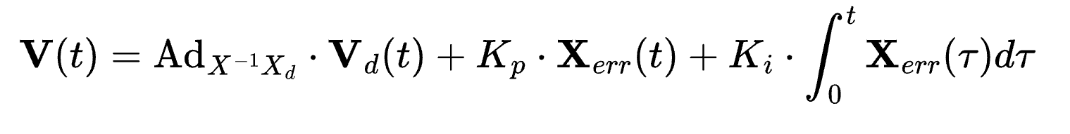
This controller combines both:
- Feedforward motion (from the reference trajectory)
- Feedback correction (based on the error between actual and desired configurations)
The function uses:
- The current end-effector configuration
- The desired configuration at the current and next time step
- PID Gain matrices
- The time step
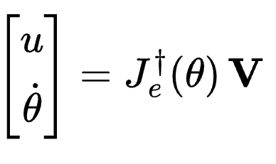
It computes the commanded twist of the end-effector, which is then converted to joint and wheel velocities using the robot’s Jacobian expressed in end-effector frame. The controller allows the robot to accurately track a planned path and correct for any small errors, enabling smooth and responsive motion in simulation.
Handling joint constraints and singularities
-
All calculations involving the inverse of Jacobians are handled with a tolerance to prevent very large values in the inverse when the Jacobian is near singular (i.e., eigenvalues near zero). This avoids unrealistically high commanded speeds.
-
Speed limits are applied to the arm joints and wheels to keep the simulation closer to real-world behavior.
-
Joint limits were determined experimentally using Scene 3 in CoppeliaSim (Interactive YouBot).
-
If an arm joint is about to exceed its limit in the next time step, the corresponding column in the manipulator Jacobian is set to zero. This update is applied to all joints predicted to exceed their limits.
-
A new commanded twist is then calculated based on the modified Jacobian.
-
This approach is simple but conservative. It restricts robot motion even when additional movement is technically safe or needed:
- For example, the method failed during a task using a poorly tuned feedforward + PI controller (with overshoot and enhancements). The robot briefly needed to exceed some constraints to meet the control demands, but the strictlimits prevented this, leading to high error, unstable motion, and task failure.
- However, the same method succeeded in a scenario without enhancements, as no constraints were violated.
Results
Code
All code and simulation outputs are available at https://github.com/phanikiran1169/RoboticManipulation
References
- K. M. Lynch and F. C. Park, Modern Robotics: Mechanics, Planning, and Control. Cambridge, U.K.: Cambridge Univ. Press, 2017